


The best thing I did my freshman year at Ohio State was join the Buckeye Space Launch Initiative (BSLI) Avioncis subteam. It taught me a ton and it helped me make a ton of great friends. I spent the majority of my time, designing and 3d printing the avionics bay. This opportunity was the perfect introduction to an engineering club. It let me take something I had done in high school (CAD/3D printing) and apply it in a way that visibly benefitted the entire rocket.
While I was familiar with CAD, I was significantly less familiar with all of the electronic systems that were going on inside of the bay. With the help of some of the older engineers, I began to familiarize myself with the various components that made the flight computer work. The most magical component was always the clubs custom flight computer. Built of 4 seperate PCBs, it blew my mind that it was designed by students just a couple years older than myself. While I knew they had put countless hours into it, I was drawn to the design. Every single trace had been drawn out by hand. Every single component was placed by hand. It seemed like something way too complicated for a bunch of students to come up with. At the end of the year, they ordered the next revision, and they put all of the Avionics members names on the back of the board.
After seeing my name on the circuit board, I made up my mind. I knew it would be hard, but I wanted to make my own board. I asked one of the older students how he learned to make PCBs and he directed me to a YouTube video by Phil's Lab. An almost 3 hour long tutorial video, that took me almost 9 hours to get through. Well it took a while, he was right. That video along with a couple others taught me what I needed to get started with PCB design. The question then became, why do I need a PCB.
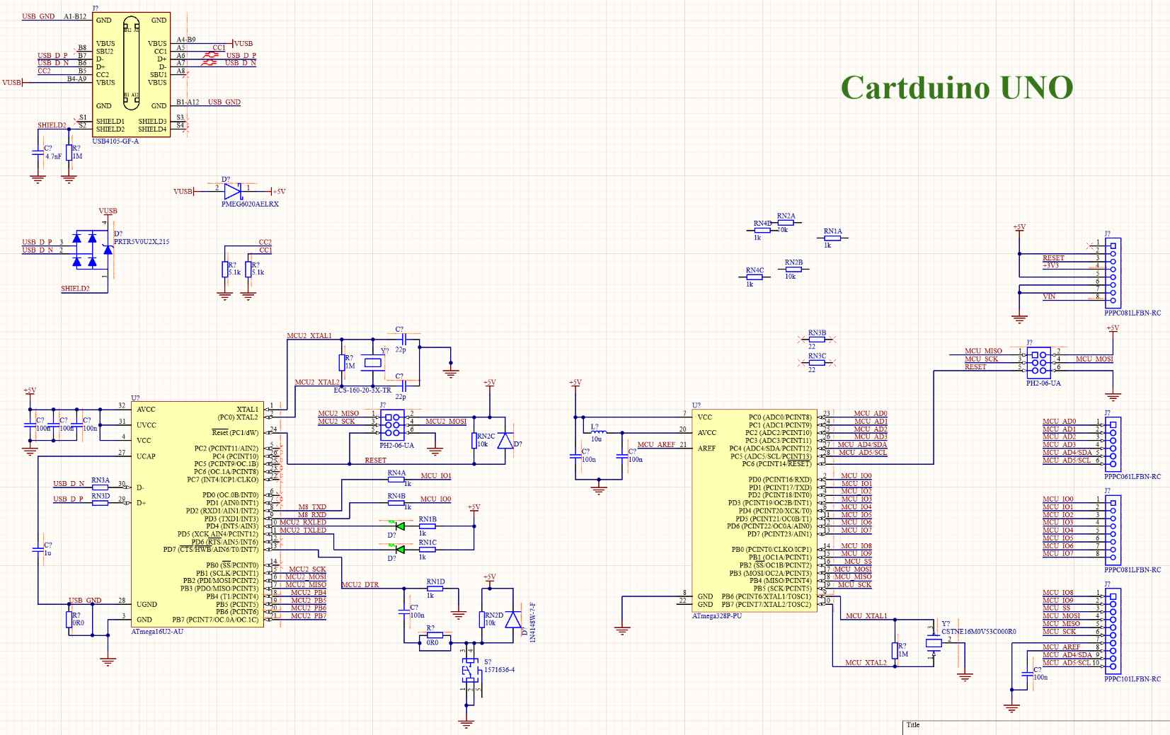
My mind instantly went to Arduino. Like CAD, it was something I had gotten familiar with during High School. Even better, the schematics for their boards were public. I thought that would be good thing because it improved my chances that the board would actually work. It also meant I would have some sort of use for the board after assembling it. I decided to name it The CartDuino (a combination of my name and Arduino).
Unfortunately, I bit off more than I could chew with the CartDuino. The more I worked on it, the more I began to wonder why I was making it? It was going to end up costing way more than an actual official Arduino, and be less functional. I also had a ton of work to go.
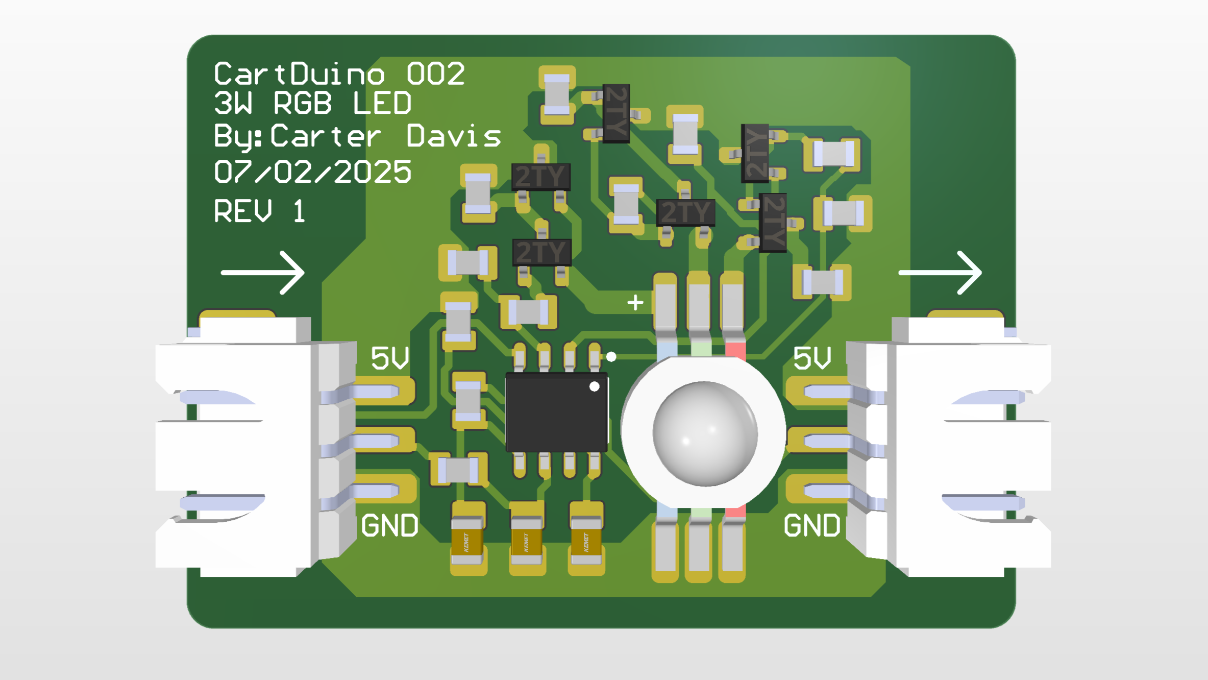
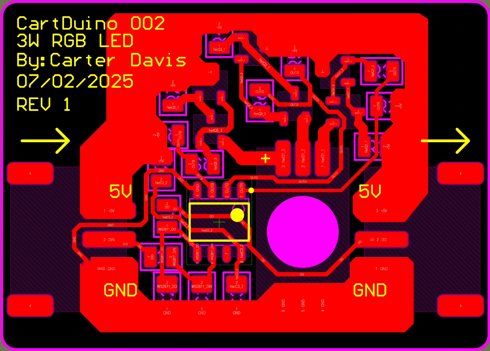
So I decided to cut my losses, and move on to the CartDuino 002. I began trying to think of another circuit board I could make. I eventually came up with the 3W RGB Neopixel I had used for the Pace Pioneer. It was only a single layer PCB, it only had about 20 components, and I knew how to program it. It was also small enough and cheap enough that I didn't have to worry about losing a ton of money if I screwed it up. There was only one issue. The schematic wasn't public. Uh oh.
Now I think about it and I realize I could've designed my own circuit to drive the LED, but at the time I was super worried and I just wanted it to work. So I got out my multimeter, I set it to test for continuity, and I began to poke around at the board and try to figure out which traces were connected to each other. It took way more time than I'm willing to admit, but after a long while, I figured it out, and I connected everything that I thought was connected.
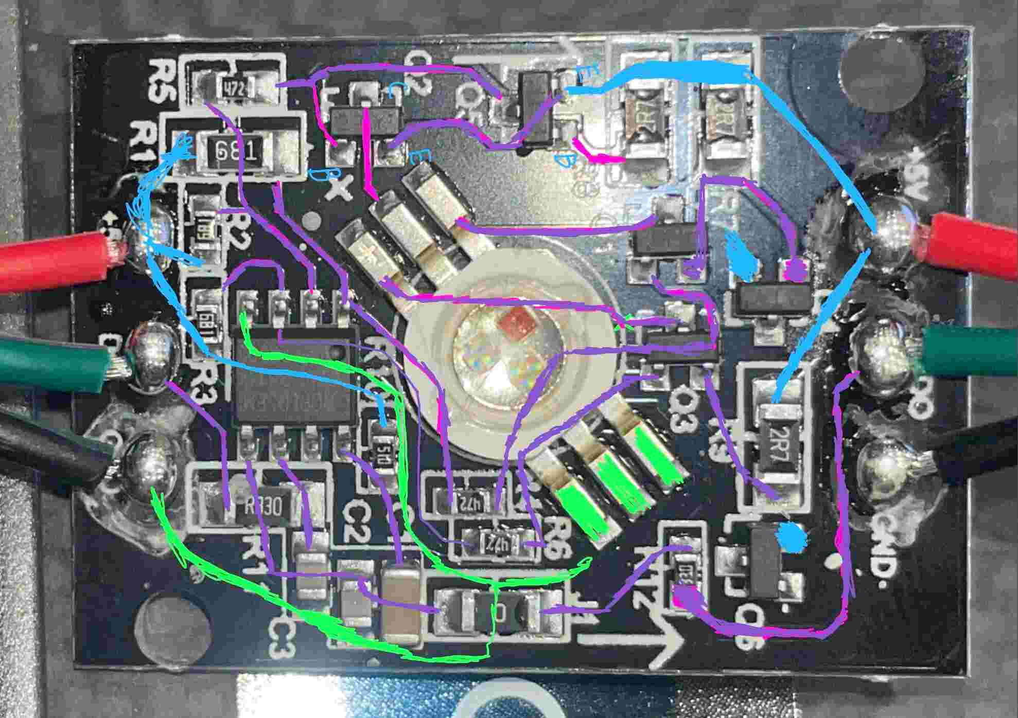
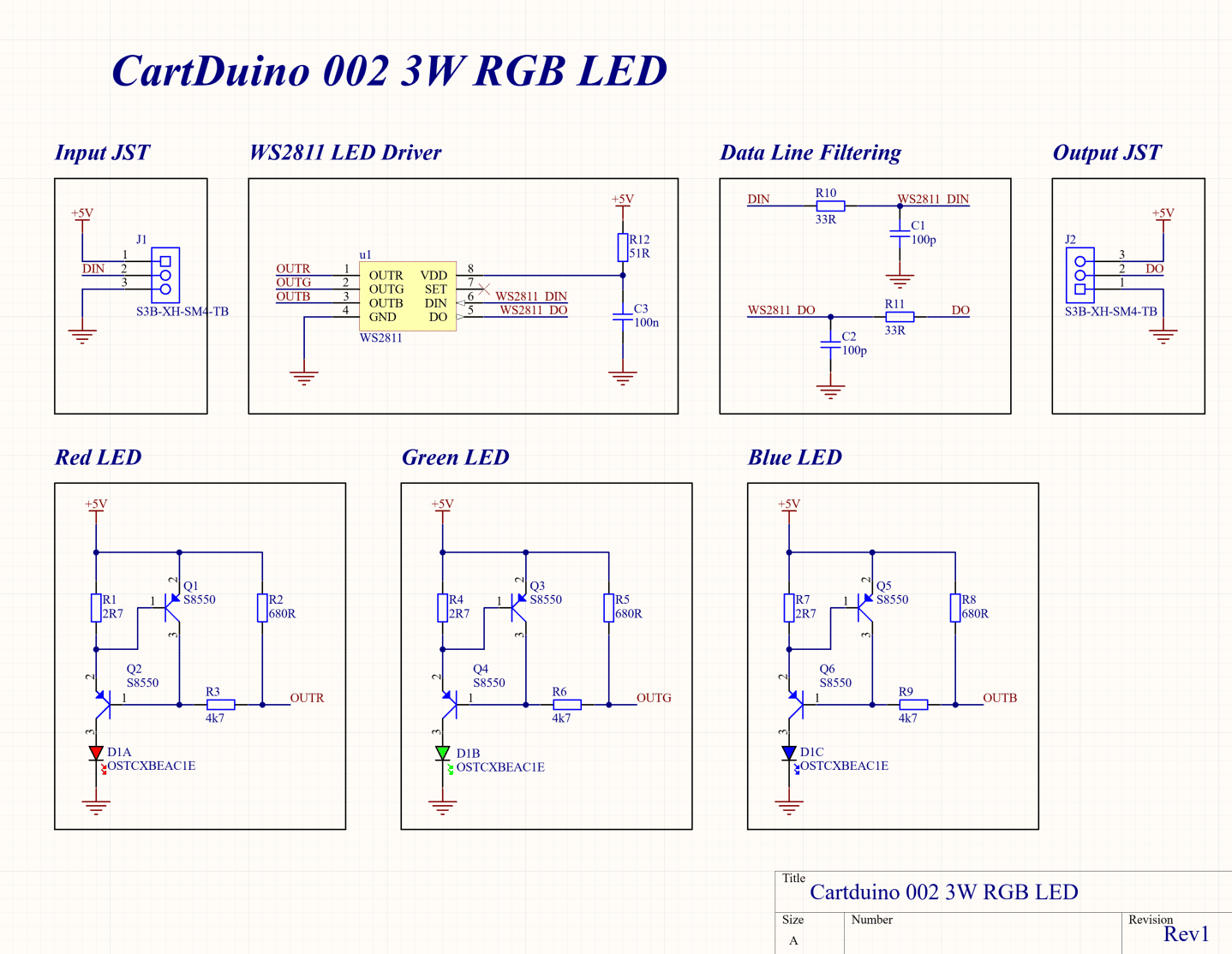
However, I still wasn't confident in the design. Their design used Bi-Polar Junction Transistors. Besides knowing that a transistor is a switch that keeps getting smaller, I had no clue how a transistor actually worked, and I wouldn't learn about them in my classes for another two semesters. So I decided I needed to simulate the circuit. I recreated the circuit in Falstad, and it after a little bit of tweaking, I got it to work. This finally gave me the confidence to dive back into Altium Designer.
All the time I spent working with the circuit in Falstad gave me a much better understanding of how the circuit actually worked. This made the schematic process way easier, and I finished it in just a couple of days. When I ran the design rule check, everything was ok. I had actually finished my first schematic. What once seemed impossible felt way more achievable.
After the schematic was finished, I moved onto the layout. Like the Adafruit board I had purchased, I decided to make an aluminum PCB. This forced everything to be placed on one layer. On one hand this made the design easier because I didn't have to worry about vias or power planes. On the other hand it meant I had to make sure everything lined up without correctly because I didn't have vias to save me. It took a couple of tries, but I eventually got something that I was pretty happy with. (I even managed to route the board without the use of a 0 ohm jumper resistor, something that the Adafruit board had relied on.) After I had something I was happy with, I hopped on a Discord call with a couple friends and let them review my board. They had a couple suggestions, but for the most part they thought it was good. I finally had a board ready to be ordered.
When I finally got the boards/components in the mail, I decided to assemble the board in my toaster oven Reflow Oven. The reflow thankfully went well.
The last couple of steps involved crimping the JST wire connectors and then adapting the software from the Adafruit board to my board. When all was said and done, I had a blindingly bright RGB light, that someday might power a Pace Pioneer V2.
And that's where I'm going to leave this project. It wasn't without it's hiccups, but it taught me a lot about PCB design. CartDuino 002 will always be my first custom PCB, but it most definitely won't be my last. I hope to take the skills I learned working on this project to build more complex circuit boards in the future.
P.S. If you go to Ohio State and want to learn how to reflow solder, I have a couple of extra CartDuino 002 boards and I would love to teach you how :)