


During the Fall semester of my third year of college, I had to take a controls class. I was relatively unaware of what the class would be about, but it was the only Aerospace Class I had to take that was taught by an electrical engineer. So I figured it fit pretty well into my niche. Well I knew I was going to learn various things in class, I also knew that real world experience is the best way to learn. I figured my bet was to design my next CartDuino PCB around controls. After a little research into the topic, I decided I wanted to build a self balancing robot.
This decision was largely influenced by YouTube Videos by Mark Rober, Hugh Phan, and Aaed Musa. They each made their balancing robots in slightly different ways, but the formula was relatively simple. The robot will actively balance on two parallel wheels controlled by a computer. The computer uses an Inertial Measurment Unit to determine the position of the robot. The computer than controls the position of the robot using a Proportional Integral Derivative (PID) controller.
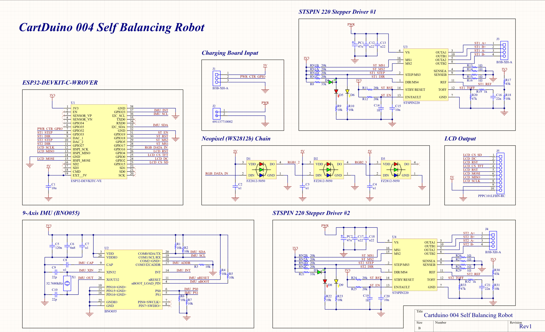
I began designing the hardware at a high level. I knew I would need two motors. The board would need to be able to control those motors, so I needed two motor drivers. In additon, the board would need to be able to determine it's position, so I needed an IMU. I picked the IMU first. I chose the BNO055 because I had used it in the past for a different project, and I found a good tutorial for using it by Paul McWhorter. So then I went back to deciding what motor I wanted to use. I decided on Stepper Motors. I figured the ability to determine the position would make them easier to control than a regular motor. Finally, in order to control the board, I needed a microcontroller. I ended up choosing the ESP32 Wrover because I already had one, and I had figured out how to connect it to a PS3 controller.
Knowing that this board was going to go hand and hand with my power board (CartDuino 3 also played in some of the design decisions)
Add a picture of the
Before I ever opened Altium, I began reading the datasheets for the parts I was going to use. I worked off the reference schematics and drew out the circuits for the IMU and the motor drivers.
Picture of the hand drawn circuits
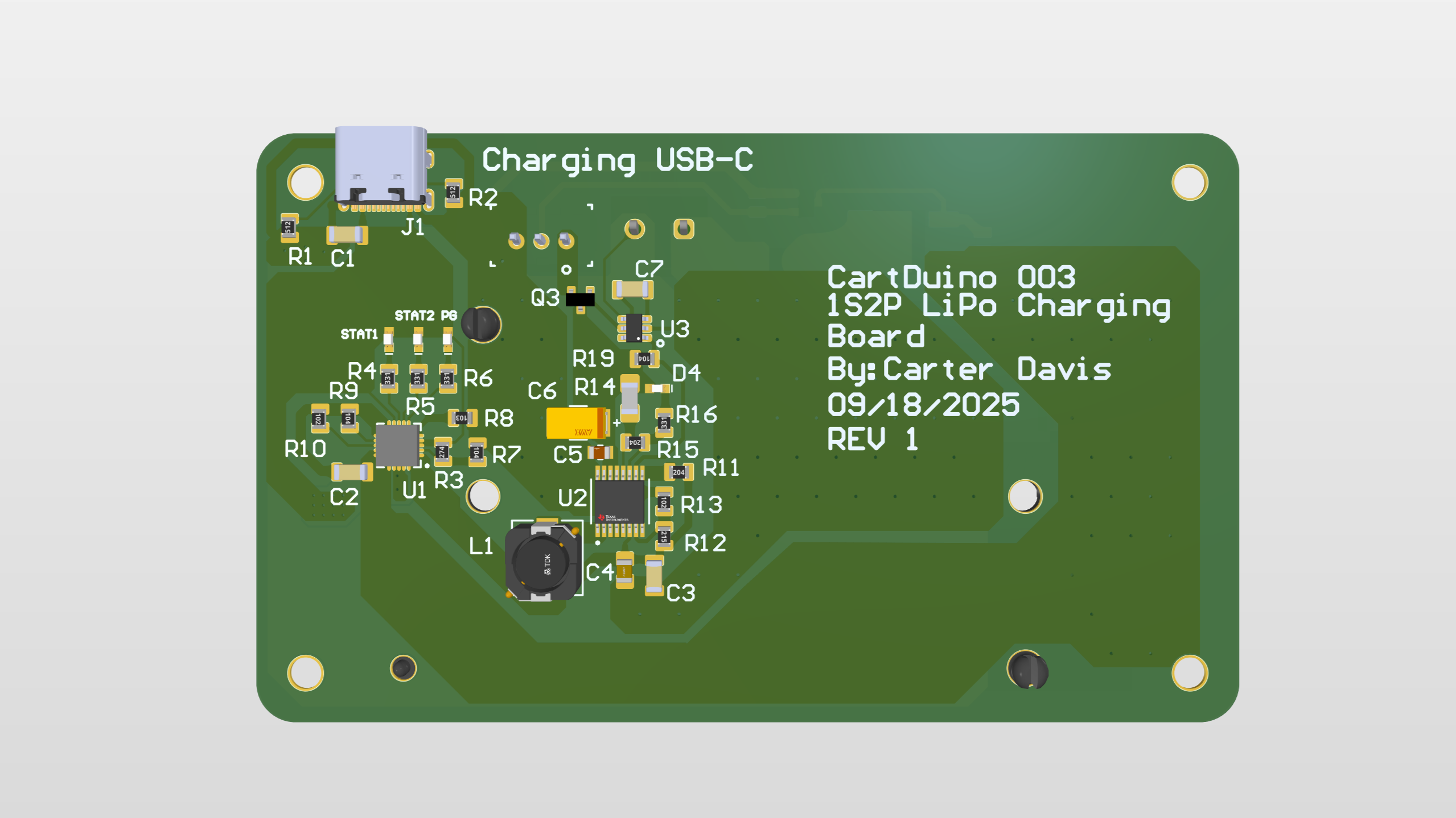
Eventually, I made it into Altium and began the schematic work within Altium. When I finished laying out the motor drivers and IMU, I realized I still had a lot of leftover GPIO pins. I began brainstorming different things I could add to the board, and I came up with the idea to add an LCD screen. I had never worked with an LCD, and it seemed like something cool that I could add. That took me down to one last pin, so I took some inspiration from CartDuino 002 (the RGB Light board) and added some RGB lights. At that point my schematic was finally done.
Moving on to the layout, I decided to try a four layer board for the first time ever. Well I probably could have done the layout with two layers, having a ground/power plane made the layout significantly easier. Besides that, the layout went relatively smoothly, and I was eventually ready to order the boards. Recieving the boards was super exciting. The second I had my hands on all of the components, I began assembling this board.
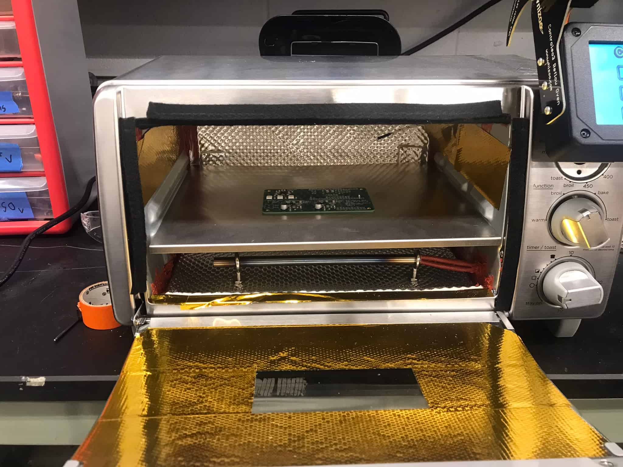
Assembling the board was a little bit of a challenge, but I had prepared the best that I could. I ordered the boards, the components, the stencil, and solder paste. For reflow, I had already contructed a Controleo 3 reflow oven out of a toaster oven. I also 3D printed two right angles to hold the board in place. It took a couple of hours, but I put down the solder paste and put all of the components in place. The board was then reflowed inside of the oven.
At this point, I was super excited, the board looked great. It was awesome to see something that I had spent so much time on, be brought to life. Unfortunately, that excitement soon began to fade. When I plugged in the ESP32, everything totally fell apart. I couldn't get any acceleration readings from the IMU. The stepper motors wouldn't spin. Even the RGB LEDs wouldn't work. The only thing that worked was the lcd screen (aka the thing I cared about least). I was honestly heart broken, but I wasn't ready to quit.
I began testing with the LEDs because they felt like the simplest thing to fix. They only needed power, ground, and one data line. I eventually tested it with a different pin than the one I had assigned, and they turned on. Seeing them light up was an awesome moment, but why didn't they work with the original pin. It turns out the specific ESP32 that I was using (WROVER), had that pin disabled, as it used it for extra memory. I had bought the WROVER thinking there was no downside, to the extra memory option, but I was obviously wrong. Thankfully, it was an easy enough fix. I just had to order the board without the extra memory (WROOM), and all was fixed.
Picture of the LEDs lighting up on the board
I then moved on to the inertial measuremnt unit (BNO055). My initial thought was that I had screwed up soldering the component as it had pins hidden on the underside of the chip. So I went and spent hours at the hot air station, soldering/desoldering the chip. After every attempt, I still couldn't get any readings from the chip. I spent so long doing this that I ended up ripping 3 of the pads off of the bottom of the chip. I had ordered a spare, but this made me contemplate whether the way the chip was attached was the issue. So I went to the datasheet, and I found on page 18 "For the switching sequence of power supply VDD and VDDIO it is mandatory that VDD is powered on and driven to the specified level before or at the same time as VDDIO is powered ON." So I desoldered the capacitors right next to the VDDIO pin, and everything began to work again.
Gif of the lights changing based on the orientation of the board
After the inertial measuremnt unit was working, I moved on to the stepper motor driver (STSPIN220). Obviously the motor wasn't working, but as I dug into it more, I realized that the motor wasn't drawing any current. After looking over the datasheet, I found that the enable pin was being pulled low because a fault was being triggered. I suspected that the issue was related to the two motor drivers sharing an enable pin. So I put together some extra components on an extra board, to test one motor at a time. With this second board, everything worked, so I decided to cut the enable trace that was shared between the two drivers. This didn't fix anything, which had me truthfully stumped. After looking over the original board once again, I realized that some of the resistors were in the wrong orientation. They were in a horizontal orientation when they were supposed to be in a vertical orientation. The motors were never going to work in this orientation. So I went back to the hot air station, and rotated the resistors. Well doing this, I accidentally knocked one of the motor ICs off, and I was unable to get it back on. I'm currently in the process of ordering new components to make a new board from scatch, but I'm optimistic that this one will work.
- Fix the motor controller PCB
- Begin work on the PID controller
- 3D print the robots shell